- +86-18123742490
- marketing@senseiot.com
- 周一至周五 9:00-18:00
制造商:: -
Product datasheet: TGS2600.pdf
Digital humidity & temperature sensor — specification summary
Applications: Features:
* Low power consumption * High sensitivity to gaseous air contaminants * Long life and low cost * Uses simple electrical circuit * Small size
* Air cleaners * Ventilation control * Air quality monitors
The sensing element is comprised of a metal oxide semiconductor layer formed on an alumina substrate of a sensing chip together with an integrated heater. In the presence of a detectable gas, the sensor's conductivity increases depending on the gas concentration in the air. A simple electrical circuit can convert the change in conductivity to an output signal which corresponds to the gas concentration.
The TGS 2600 has high sensitivity to low concentrations of gaseous air contaminants such as hydrogen and carbon monoxide which exist in cigarette smoke. The sensor can detect hydrogen at a level of several ppm. Figaro also offers a microprocessor (FIC02667) which contains special software for han- dling the sensor's signal for appliance control applications.
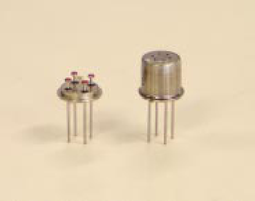
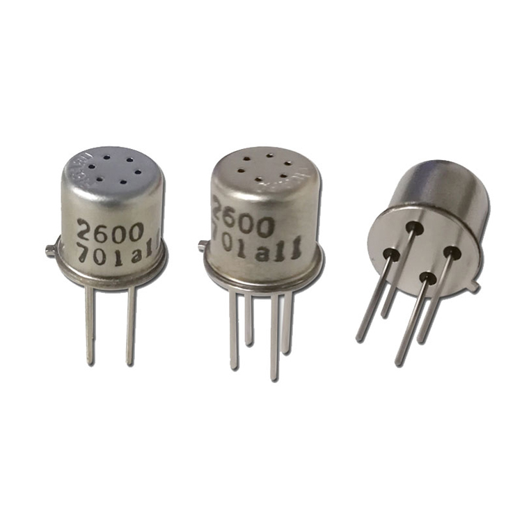
Due to miniaturization of the sensing chip, TGS 2600 requires a heater current of only 42mA and the device is housed in a standard TO-5 package.
The figure below represents typical temperature and humidity dependency characteristics. Again, the Y-axis is indicated as sensor resistance ratio (Rs/Ro), defined as follows: Rs = Sensor resistance in fresh air at various temperatures/humidities Ro = Sensor resistance in fresh air at 20 ° C and 65% R.H.
The figure below represents typical sensitivity characteristics, all data having been gathered at standard test conditions (see reverse side of this sheet). The Y-axis is indicated as sensor resistance ratio (Rs/Ro) which is defined as follows: Rs = Sensor resistance in displayed gases at various concentrations Ro = Sensor resistance in fresh air
Temperature/Humidity Dependency: Sensitivity Characteristics:
Sensor Resistance Ratio (Rs/Ro)
Air Methane
Carbon monoxide
Iso-butane Ethanol Hydrogen
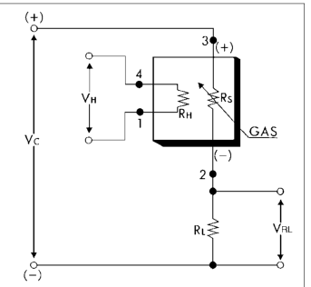
Basic Measuring Circuit:
The sensor requires two voltage inputs: heater voltage (V H ) and circuit voltage (V C ). The heater voltage (V H ) is applied to the integrated heater in order to maintain the sensing element at a specific temperature which is optimal for sensing. Circuit voltage (V C ) is applied to allow measurement of voltage (Vout) across a load resistor (R L ) which is connected in series with the sensor. DC voltage is required for the circuit
voltage since the sensor has a polarity. A common power supply circuit can be used for both V C and V H to fulfill the sensor's electrical requirements. The value of the load resistor (R L ) should be chosen to optimize the alarm threshold value, keeping power consumption (P S ) of the semiconductor below a limit of 15mW. Power consumption (P S ) will be highest when the value of Rs is equal to R L on exposure to gas.
r e b m u n le d o M 0 0 B - 0 0 6 2 S G T
Top view
e p yt t n e m ele g nis n e S 1 D
e g a k c a p d r a d n a t S n a c la t e m 5 - O T
ø0.5 x 6
ø8.1 ± 0.2
e g a tlo v r e t a e H V H 0 . 5 ± C A / C D V 2 . 0
Sensing element
tiu c ric d r a d n a t S s n oitid n o c
e g a tlo v tiu c ri C V C 0 . 5 ± C D V 2 . 0 s P ≤ W m 5 1
e c n a tsis e r d a o L R L elb air a V k 5 4 . 0 Ω . ni m
Side view
ytivitis n e S ) s R f o oit a r e g n a h c ( 6 . 0 ~ 3 . 0 H f o m p p 0 1 ( s R 2 ) )ria ( s R
Bottom view
s n oitid n o c s a g ts e T ria la m r o n 0 2 t a ± 5 6 , C ˚ 2 ± H R % 5
ø5.1
ts e t d r a d n a t S s n oitid n o c
s n oitid n o c tiu c ri C V C 0 . 5 = ± C D V 1 0 . 0 V H 0 . 5 = ± C D V 5 0 . 0
Pin connection: 1: Heater 2: Sensor electrode (-) 3: Sensor electrode (+) 4: Heater
d oir e p g nin oitid n o C ts e t e r o f e b s y a d 7
| heater voltage (V | H ) and circuit voltage | A common power supply circuit can be | |||
|---|---|---|---|---|---|
| (V ). The heater voltage (V | ) is applied | used for both V | and V | to fulfill the |
| (Vout) across a load resistor (R | L ) which | 15mW. Power consumption (P | S ) will | |
|---|---|---|---|---|
| is connected in series with the sensor. | be highest when the value of Rs is | |||
| DC voltage is required for the circuit | equal to R | L on exposure to gas. |
| T a r g e t g a s e s | A ri c o n t a m ni a n st | |
|---|---|---|
| T y cip la d e t e oitc n r a n g e | 1 ~ 3 0 p p m o f H 2 | ø9.2 ± 0.2 |
| yt( cip )la | ||
|---|---|---|
| H e a t e r c u rr e n t | I H | 4 2 ± 4 m A |
| c h a r a tc e citsir s | P 2 1 0 m W V = 5 . 0 V D C | |
|---|---|---|
| H H | ||
| u n d e r ts a n d a r d t e ts c o n s u m p oit n | ||
| c o n oitid n s | ø0.55 ± 0.05 | |
| S e n s o r r e tsis a n c e | R s 1 0 k ~ 9 0 k Ω ni ria |
| The value of power consumption (P | S ) can | Sensor resistance (Rs) is calculated with | 4: Heater |
|---|---|---|---|
| be calculated by utilizing the following | a measured value of Vout by using the |
| (V C - Vout) | V C x R L | |
|---|---|---|
| P S = | R S = - R L | Mino, Osaka 562-8505 JAPAN |
| R S | Vout |